1966: Dudley Rickard plans to tune the Riley engine
Today I received a history about the D7 by Dudley Rickard. Dudley used the car in various races in 1966 and describes his plans at the time to tickle more horsepower out of the engine. Thank you Dudley for your information.
Preparation for the 1966 racing season.
By this time I was one of the founding members of the Historic Racing and Sports Car Club – conceived by Guy Griffiths (a well known motor sport photographer whose daughter Penny, raced a Jaguar engined Silverstone D48 GAY 473) and Betty Haig, amongst others – and was keen to take part in events that they supported. However I felt that D7 was underpowered when compared to the cars it would be racing against – C Type Jaguars, Allards, Frazer Nash Le Mans Replicas…so I started to research the options.
My first task was to locate a Riley Pathfinder engine, which I eventually found in a breaker’s yard half a mile from where I lived in Twyford Berks.
My plan was to start the season using my newly rebuilt RMF engine and during this time prepare and tune the RMH Pathfinder engine. At the time I noted the potential of the Pathfinder RMH engine in standard tune which developed 110hp @ 4,400rpm as opposed to the 104hp @ 4,500 of the RMF engine installed in the Silverstone that had to run at an increase of 100rpm to gain that extra 4hp over the standard RMF engine fitted to Riley saloons.
Tuning the RMF.
This section is perhaps academic as I never implemented my plans but might prove interesting to future owners.
My first approach was to ask Harold Dermott (Brian Dermott’s brother who was at Birmingham University studying engineering and later was to have a successful career as production director of McLaren Automotive).
I asked him two simple questions: “What is the maximum horsepower the Riley RMF engine can reliably deliver. And what do I need to do to achieve it?”
After pages of calculations the answers came back as follows:
- Increase the compression ratio from 6.9:1 to 8:1
- Inlet valve timing
- Open 20° B.T.D.C.
- Close 53° A.B.D.C.
- Exhaust
- Open 55° B.B.D.C.
- Close 30° A.T.D.C.
- Fit 1¾ inch S.U. carburettors or fit richer needles to existing 1½ inch carburettors. (Mixture should be 20-25% rich for maximum volumetric efficiency)
- New Exhaust with tuned lengths.
- Do not increase valve lift as with an 8:1 compression ratio there is the possibility that the piston will hit the valves.
- Port and tune carburettor inlet pipes and install inlet cold box rather than take hot air from under bonnet.
- Ignition timing 6°-10° B.T.D.C.
Estimated performance:
- Absolute rev limit; 5,500 rpm.
- Maximum bhp @ 5,000 rpm 61.5 bhp/litre = 150 hp
- @ 5,500 rpm 67.5 bhp/litre = 165 bhp
All this I found encouraging as it put the Healey within a whisker of the Frazer Nash’s Bristol engine power to weight ratio.
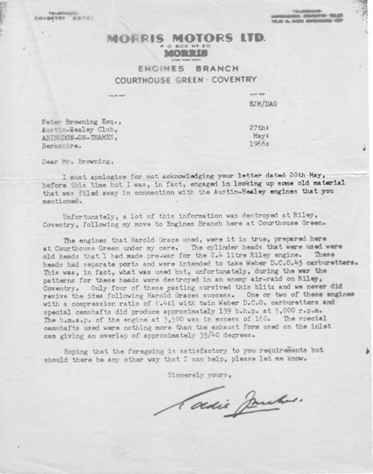
As part of this process I contacted Peter Browning ex-manager of the BMC Competition Department to see if any of the eight port cylinder heads developed pre-war for Howard Grace were still available. The answer from Eddie Maher at the Morris Motors engine plant was very interesting and indicated that the RMF engine with this cylinder head had great potential:
Performance summary of Riley RMF engine with 8 port head.
- Compression ratio; 8.4:1
- Power: 139 bhp at 5,000 rpm.
- BMEP: 160 @ 3,500 rpm
- Inlet camshaft; profile a copy of exhaust form
- Overlap: 35º/40º
- Carburettors; Twin Weber D.C.O.45
Note: Harold Grace raced Riley saloon cars between 1950 – 1957. During the 1956 -57 seasons he raced a Riley Pathfinder.
The proposed new exhaust system played an important part of my tuning plan. As my sketch showed I chose a system based on ‘Independence Working’ (where individual tuned pipes are led to the silencer or collector box) as opposed to an ‘Interference Working’ system where shorter exhaust pipes are joined together to help scavaging. I felt that the ‘Independence Working’ system was better suited the characteristics of the RMF engine.
The key issue was calculating the length of these pipes. In his excellent book ‘Scientific Design of Exhaust and Intake Systems’ (Philip H Smith A.M.I. Mech.E. 1962 G.T Foulis & Co. Ltd London – available on the internet) sets down the formula for calculating the length of these primary pipes as:
Primary pipe length in feet = AxSxD2
1,400xd2
Where: A = Exhaust valve opening period in degrees of crankshaft rotation.
S = Stroke length in inches.
D = Cylinder bore in inches
d = Exhaust valve port diameter in inchesa
As a final investigation I contacted Geoff Healey and asked if they had ever considered developing a higher performance Silverstone.
The answer was yes.


